Project Overview
This project is part of ongoing assistive robotics research in developing a lower-limb pediatric exoskeleton for children with cerebral palsy.
My contributions:
(1) feedforward motor control to reduce resistive drag from back-EMF and rotor inertia
(2) mechanical design of the hip joint assembly to accommodate pediatric anatomy and natural gait kinematics.
Hardware: CubeMars QDD BLDC motor · Novanta Everest CORE servo drive
Control Architecture
The exoskeleton runs a layered software stack bridging high-level control logic down to the Novanta Everest servo drive.
A Python controller library — including force-feedback, oscillatory, and state-machine walking modes — computes desired torque commands. ROS 2 carries these commands as messages between nodes. From there, commands travel down through a robot model layer (which converts degrees to encoder ticks) and a hardware abstraction layer over SPI to reach the drive.
The Novanta Everest CORE handles low-level closed-loop control. Internally it runs a cascaded PID pipeline: position → velocity → torque → current → voltage. A state machine safety check gates all setpoints before they reach the MUX and setpoint manager, which supports linear, trapezoidal, S-curve, and PVT motion profiles.
Communication between the ROS 2 host and the microcontroller uses UDP sockets. TCP is used separately for tuning and calibration commands.
Back-EMF & Inertia Feedforward
Problem
At the drive level, the AKE60-8 motor exhibits Back-EMF drag and rotational inertia that fight the patient’s natural leg motion. Both effects are especially problematic in a transparent control, where the goal is to make the device feel as if it isn’t there.
Approach
A feedforward term is injected at the torque junction every control tick, computed from the drive’s real-time velocity and acceleration feedback:
$$ \tau_{feedforward} = (K_{back-emf} \cdot \omega) + (K_{accel} \cdot \alpha) \\[6pt] \tau_{commanded} = \tau_{desired} + \tau_{feedforward} $$Experimental Results
Three phases were tested:
- Phase 1 — No feedforward (baseline)
- Phase 2 — Back-EMF feedforward only
- Phase 3 — Back-EMF + acceleration feedforward
Test 1: Manual rotation (transparency mode)
With position/velocity gains zeroed and FF off, rotating the shaft by hand produces back-EMF braking current. Adding the feedforward term cancels the induced current, making the joint feel free to rotate.
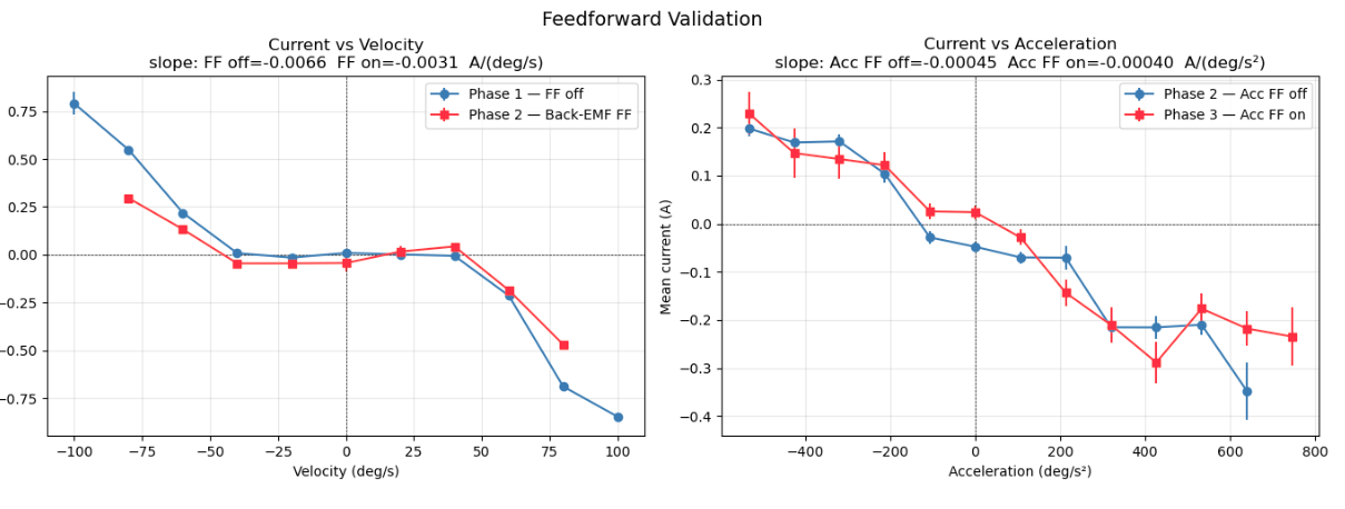
- Velocity–current slope: −0.0066 → −0.0031 A/(deg/s) (Phase 1 → Phase 2)
Test 2: Sinusoidal position trajectory
With position and velocity feedback active, a sinusoidal trajectory was commanded. The feedforward reduces the current the drive must supply to sustain the commanded motion.
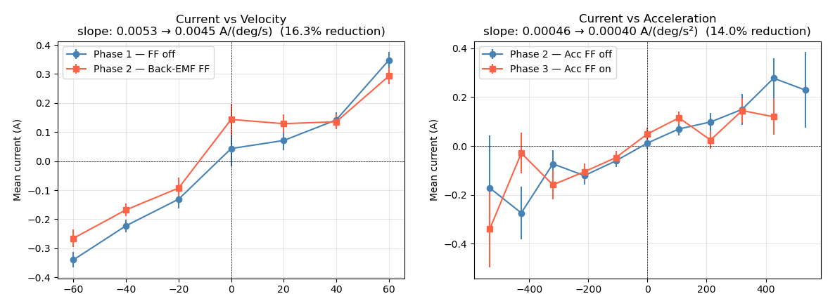
- Velocity–current slope reduction: 16.3% (0.0053 → 0.0045 A/(deg/s))
- Acceleration–current slope reduction: 14.0% (0.00046 → 0.00040 A/(deg/s²))
Across both tests, mean current draw decreased monotonically from Phase 1 → Phase 2 → Phase 3, confirming that back-EMF and inertia compensation together reduce the resistive load felt by the patient.
Mechanical Design
The hip joint assembly was designed from scratch around four pediatric-specific requirements:
- Low inertia — minimizing distal mass to reduce metabolic cost and improve transparency
- Hip abduction/adduction freedom — ±30° range of motion to accommodate natural pediatric gait
- Discrete link length adjustment — quick-change slot mechanism to fit different leg lengths without tools
- Self-aligning mechanism — passive compliance to prevent kinematic misalignment between the robot joint axis and the patient’s anatomical hip axis
Key Design Features
90° Torsional Spring (Hip Ab/Ad Joint) A torsional spring allows the lateral linkage to passively follow the patient’s hip during abduction and adduction while returning to neutral alignment when unloaded. A 30° hard stop limits maximum abduction to protect the joint and the patient.
Discrete Link Length Adjustment A slotted bracket with indexed hole positions enables rapid length adjustment across the femoral link. This allows the exoskeleton to be reconfigured between patients without requiring custom hardware.
Tech Stack: SolidWorks · Python · ROS 2 · Novanta Everest SDK · CubeMars AKE60-8